NEMA Wiring Schematic Manual for Electrical Experts
Approximately 70% of electrical breakdowns in facilities stem from poor wiring practices. This fact underlines the need of complying with set guidelines, spotlighting NEMA wiring schematics’ significance for electrical professionals. Via these diagrams, wiring arrangements that meet both operational effectiveness and optimal protection standards are presented.
The aim of this document is to equip electrical practitioners with deep insights into NEMA criteria. Stressing the significance of correct electrical installations is essential. Through mastering these rules, practitioners can substantially reduce the likelihood of hazards and guarantee they comply with safety measures supported by Installation Parts Supply. Expertise in l14-30 plug wiring diagram is vital whether creating new setups or repairing present ones, as it improves the capability to offer secure and dependable electrical systems.
Principal Conclusions
- NEMA wiring schematics are essential for guaranteeing electrical protection and conformity.
- Correct wiring practices can minimize electrical malfunctions substantially.
- Understanding NEMA criteria enhances the effectiveness of electrical installations.
- Installation Parts Supply promotes compliance with safety protocols in electrical tasks.
- NEMA schematics cover a wide range of applications across different industries.
Grasping NEMA Norms and Their Significance
NEMA criteria are crucial in the electrical domain, guiding protection and functionality precisely. Developed by the National Electrical Manufacturers Association, they set key standards for developing, testing, and labeling electrical appliances. It ensures standardization and dependability across all electrical installations, which is invaluable.
What Are NEMA Norms?
NEMA classifications differ from levels 1 up to 13. Every level defines the criteria required for electrical appliances to perform efficiently. For example, NEMA 1 delivers fundamental indoor safeguarding but lacks dust shielding. Conversely, NEMA 4 guarantees equipment is waterproof, a requirement for enduring significant water contact. Understanding these designations is crucial in choosing appropriate appliances.
How NEMA Standards Are Important for Electrical Safety
The impact of NEMA criteria in ensuring electrical safety is substantial. They are instrumental in lowering electrocution risks, equipment failures, and fire dangers. Proper adherence to NEMA ratings enables equipment to perform safely under particular surrounding conditions. For open-air deployment, NEMA 3 classifications provide protection against the weather, safeguarding the equipment from harsh weather like precipitation and blizzard conditions. In regions susceptible to explosions, standards including NEMA 7, 8, and 9 are essential for maintaining safety.
Implementations of NEMA Criteria in Wiring Drawings
The use of NEMA criteria in wiring drawings is crucial for secure, efficient electrical setups. These schematics employ standardized symbols and structures derived from NEMA classifications, simplifying the understanding of intricate electrical configurations. Such standardization is advantageous. It promotes transparency, consistency, and minimizes errors, thus improving electrical safety across home and commercial landscapes.
NEMA Wiring Schematic Fundamentals
NEMA wiring diagrams are vital for electrical experts, making complicated linkages transparent. They outline the junctions and parts in various configurations. By grasping the components, types, and symbols of NEMA diagrams, professionals can improve their work in installations and upkeep.
Constituents of NEMA Wiring Schematics
NEMA drawings comprise crucial parts for distinct electrical installations. You’ll find wiring endpoints, connectors, and various equipment for reliable connections. Each piece secures energy is spread optimally, following security standards.
Types of NEMA Wiring Diagrams
NEMA employs multiple diagrams, like connection blueprints and electrical designs. Schematics depict appliance interconnections, while layouts show current flow. Selecting the appropriate drawing helps with problem solving and deployment.
Common Notations Employed in NEMA Wiring Drawings
Notations in wiring drawings are essential for unambiguous communication. They depict switches, loops, and couplers. Recognizing these icons helps crews comprehend diagrams accurately. Such practice ensures configurations meet NEMA standards.
NEMA Wiring Schematic Characteristics
For electrical experts, understanding the core aspects of detailed electrical wiring schematics is essential. These schematics provide both clarity and completeness, aligning configurations with NEMA criteria. They require precise annotation and proportioning to minimize setup mistakes. This fosters a safer and more efficient operational setting.
Primary Attributes of Precise Electrical Wiring Schematics
Accurate electrical wiring diagrams are vital in electrical initiatives. They embody crucial qualities such as:
- Clarity: Diagrams should be straightforward, minimizing the risk of misinterpretation.
- Wholeness: They must include all essential components, connections, and electrical standards.
- Adherence to Standards: Complying with NEMA norms is mandatory for ensuring security and performance.
- Thorough Annotation: Unambiguous labels on each component are crucial for understanding and minimizing errors.
- Correct Scaling: The scales should reflect the real setup to depict the arrangement precisely.
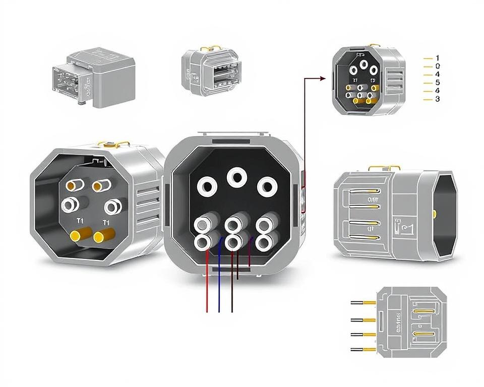
Comprehending NEMA Connector Layout
Grasping NEMA connector configuration is crucial for establishing accurate linkages in electrical setups. Awareness of specific pin configurations maintains safety and device functionality. There exists a diversity of NEMA connectors, crafted for different voltages and currents, including:
| Connector Model | Amperage Rating | Voltage Level |
|---|---|---|
| L5-15 | 15A | 125V |
| L5-20 | 20A | 125V |
| L14-20 | 20A | 125/250V |
| L1430C | 30A | 125/250V |
| L620C | 20A | 250V |
| L1430C | 30A | 125/250V |
| L630R | 30A | 250V |
Grasping NEMA coupler pinouts is vital for stable linkages, enhancing efficiency. It’s critical to match connectors with devices properly using rotary-lock or flat blade styles, to avoid dangers.
NEMA Appliance Wiring
NEMA appliance wiring covers multiple configurations for secure electrical appliance connections. These guidelines ensure that devices integrate safely, lowering risk. Understanding the various NEMA appliances and their wiring is essential for technicians.
Various Kinds of NEMA Devices
NEMA organizes units by type based on voltage levels and flow demands. Essential arrangements are:
- 2-Pole, 2-Wire
- 2-Pole 3-Wire Grounding
- 3-Pole, 3-Wire
- 3-Pole 4-Wire Grounding
- 4-Pole, 4-Wire
- 4-Pole 5-Wire Grounding
These setups find use in domestic settings and industrial facilities, supporting 125V, 208V, and 480V.
NEMA Outlet Wiring Demystified
NEMA plug wiring varies to meet diverse power needs, with locking types ensuring consistent interfaces in shaky settings. For example, the L5-15 plug works at 15 amps, typical of enterprise settings, whereas the L14-20 is crafted for 20 A at 125/250 voltage.
The NEMA designation system assists in choosing the appropriate plugs, spotlighting features like polarity and grounding. This meticulousness guarantees that appliances function safely.
NEMA Receptacle Wiring Instructions
Proper wiring of NEMA receptacles meets electrical standards and security protocols. For instance, L530R receptacles are configured for 30 A at 125 voltage, with L630R options for 250 V. Correct grounding is crucial to dodge electrical accidents.
Choosing accredited NEMA plugs and outlets secures protected, regulation-compliant configurations. It’s imperative to check official standards when implementing.
NEMA Motor Wiring and Implementations
NEMA motor wiring is crucial in electrical design, notably for manufacturing use. Knowing how NEMA motor configuration works secures that motors are integrated for best efficiency. These motors, like one-phase and tri-phase variants, demand correct wiring to function reliably and optimally.
Overview of NEMA Motor Wiring
Understanding NEMA motor wiring requires familiarity of junctions and setups. The majority of three-phase motors offer dual-voltage, signifying they can run on both low (208-230V) and high power levels (460V). Wiring at high voltage results in lower current draw than at low voltage. High voltage perks include thinner cables for the supply, a significant benefit for units exceeding 10 HP.
While both NEMA and IEC appliances are utilized in the industry, NEMA variants are typically bigger and more expensive than IEC ones for less than 100 HP uses. NEMA trips span size 00 to 9, fit for various uses. A common characteristic in NEMA trips is a Fault Class of 20, intended to trip when a motor’s draw surpasses six times the rated current in 10 seconds.
Opting for the Correct NEMA Motor Arrangement
Selecting the right NEMA motor configuration affects system efficiency and security. A typical three-wire control circuit uses three wires for a power control pushbutton panel, facilitating straightforward motor operation. Typical three-phase setups consist of the 12 Lead Dual Voltage and 6 Lead, facilitating Wye and Delta arrangements.
IEC motor starters commonly feature phase monitoring, enhancing safety. They also include adjustable Fault Classes for specific protection in low voltage levels operations. Moreover, many units have temperature safeguards, essential for single-phase and Dual Voltage configurations.
| Arrangement | Voltage Type | Amperage | Common Application |
|---|---|---|---|
| 12 Lead Dual Voltage | Dual Voltage (208-230V / 460V) | Dependent on motor size | Wye Start – Delta Run applications |
| 6 Lead | Single/Dual Voltage | Maximum 32A | Both Wye and Delta arrangements |
| Single Phase | Single Voltage | Varies (1-5 amps adjustment) | Two Speed, Two Winding applications |
| Delta Connection | High Voltage | Depending on setup | Used for Current Transformers and various setups |
Final Thoughts
Understanding NEMA wiring diagrams and norms is crucial for electrical specialists aiming to improve their expertise and adhere to electrical safety standards. These standards secure protected and high-performing electrical setups but also avert dangers associated with improper wiring. As discussed, following NEMA standards results in the improved performance of diverse NEMA appliances and setups.
For electricians, the choice of superior materials can greatly affect the result of their work. Installation Parts Supply provides a extensive selection of wiring items aligned with NEMA standards. This enables specialists to obtain critical elements for meeting these key requirements. Premium materials and deep expertise of NEMA wiring diagrams significantly elevate installation security and efficiency.
In your journey through electrical deployments, always put security and precision first. Mastering NEMA norms delivers the insight needed for applying industry standards correctly. This guarantees that each electrical connection formed meets premium norms.
Frequently Asked Questions
Which are NEMA wiring schematics?
NEMA wiring drawings showcase the configurations and junctions of NEMA-standard electrical appliances. They follow safety and operational criteria established by the National Electrical Manufacturers Association.
What makes NEMA standards important for electrical safety?
NEMA norms are essential to setting safety and performance criteria for electrical devices. These guidelines enable electrical professionals lower shock risks, device malfunctions, and burn dangers.
Identify the key parts are crucial in a NEMA wiring diagram?
Key elements in a NEMA wiring schematic comprise circuit configurations and linkage diagrams. These schematics also include thorough annotations and show the electrical system’s diverse parts precisely for setups.
Which kinds of NEMA wiring schematics are used?
Various NEMA wiring schematics cater to various needs, including circuitry for power distribution and interconnection diagrams for components. Each layout serves a distinct role in electrical setups.
Which are the typical symbols used in NEMA wiring schematics?
Common symbols in these schematics represent switches, circuit breakers, receptacles, and more. Employing these symbols facilitates clear interaction and precise interpretation of wiring schematics.
Identify the essential attributes of accurate electrical wiring diagrams?
Correctness in electrical wiring drawings is characterized by their lucidity, comprehensiveness, and clear labeling. They must align with NEMA norms to avoid errors in deployment.
Explain a NEMA connector layout?
A NEMA connector layout outlines electrical junctions at a connector, showing specific pin functions. This guarantees safe and optimal junctions in electrical systems.
What are the different types of NEMA devices?
NEMA units comprise various electrical sockets and couplers, like adapters and receptacles. They are crafted for diverse amperage and voltage levels specifications to fulfill unique application requirements.
Describe how NEMA plug wiring set up?
NEMA plug wiring is determined by particular ampere and voltage needs, complying with safety guidelines and code compliance for various electrical setups.
Which standards are there for NEMA outlet wiring?
Guidelines for installing NEMA sockets stress adhering to electrical codes, ensuring correct polarity, and picking correct cable sizes. This ensures both protection and operation in electrical configurations.
What is the method to wire a NEMA motor properly?
To set up a NEMA motor, one must comprehend its particular one-phase or three-phase configuration. Selecting the right wiring method is crucial, along with maintaining electrical protection for optimized motor efficiency.
What must be taken into account when selecting a NEMA motor setup?
Selecting a NEMA motor arrangement necessitates an assessment of the system’s power needs and functional attributes. It’s also essential to confirm suitability with pre-existing machinery for assured operation and safety.